In 2016, as part of our second-to-last year of high school engineering program, we — Bastien Bussière, Thomas Boissin, Lisa Battistini, and Léo-Nils Boissier — designed an affordable Braille printer: a 3-axis machine moving a needle to emboss a sheet of paper. The goal was to explore how such a device could be made accessible using low-cost parts.
The Braille Alphabet
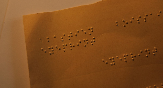
The Braille system allows visually impaired people to read using embossed paper. Each letter is represented by a combination of dots in a six-dot grid, and readers identify the letters by touch. To better understand how Braille is used in daily life, we met with several individuals with visual impairments and visited a local school for students who are blind or partially sighted. We observed how students read and interact with Braille materials, noting the importance of clear dot height, spacing, and tactile distinction. These insights directly informed our design choices for the printer, ensuring that the embossed letters would be comfortable to read and accurately represent the Braille alphabet.
A first version of the printer
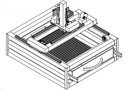
We started working on a Braille printer at the beginning of 2016. Budget was tight, so the first prototype was built in wood with belt transmission, similar to a regular printer.
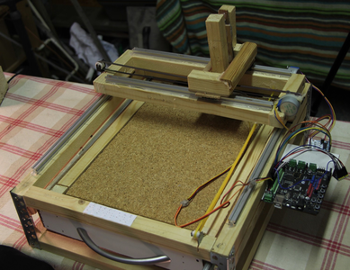
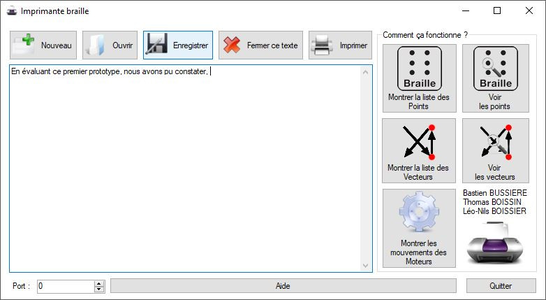
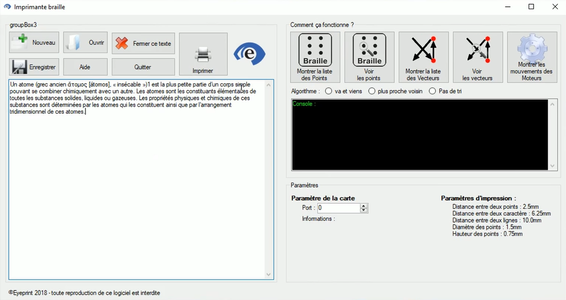
The printer used an Arduino-like controller and a C# program sending movement and embossing instructions. The software also generated the path through all dots to emboss.
This first version lacked rigidity, leading to low print precision. We therefore started a second version during our final year, with a stronger steel frame and a 3-bin paper system. Belts were replaced by leadscrews.
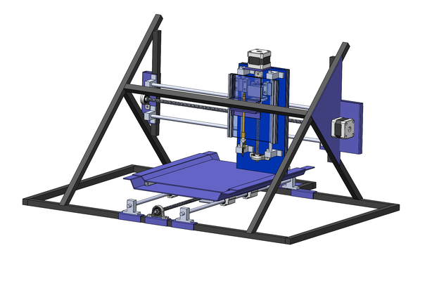
A second version of the printer
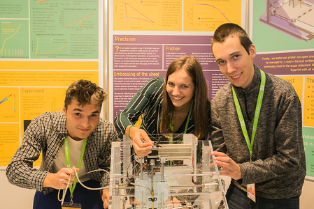
This phase focused on deeper mechanical and electrical studies. We measured the embossing force needed without piercing the sheet, tested heated needles for plastic embossing, evaluated the torque required to move the axes, and modeled deformation under load.
Beyond building, the project became an exercise in full engineering workflow: design, model, simulate, test, and iterate.
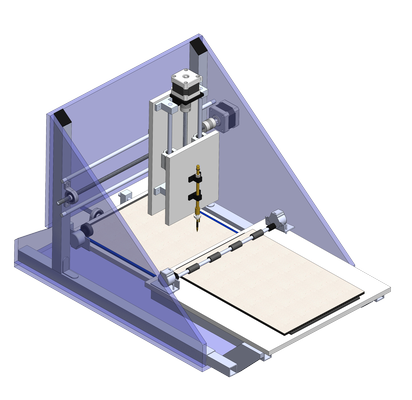
We designed a frame using 14 mm steel bars, providing high rigidity confirmed by FEM analysis. Rails and leadscrews were used on all three axes, with stronger motors to handle added mass and friction.
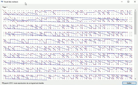
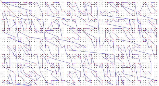
Software was refined to reduce embossing path length. Exact optimization is not tractable in polynomial time, so several heuristic methods were tested, achieving good-enough results for our needs.
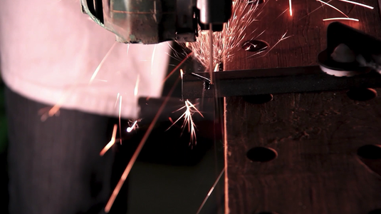
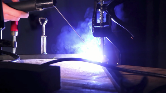
After validation, we manufactured the structure by cutting, welding, milling, drilling, and assembling.
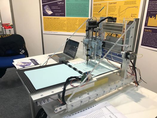
Late on the evening before the presentation, a motor failed during testing. After repairs, the prototype operated correctly and produced readable Braille samples.

The presentations
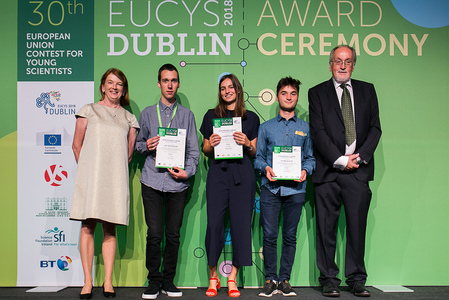
The project was presented to several juries in Lyon and Saint-Étienne, then selected for national engineering contests in Corsica, Paris and Toulouse. It was finally invited to represent France at the European Contest for Young Scientists (EUCYS) in Dublin in 2018.
The steel-frame prototype performed well but was heavy and difficult to transport. It was also damaged upon return from Corsica, so we began a third prototype with a lighter design that could be assembled and moved more easily.
A third version of the printer
This last version aimed for compactness and simplicity while keeping acceptable print quality. We repositioned the paper supply above the printing plate and replaced the steel frame with laser-cut plexiglass. A local company, ATMP INDUSTRIE PLV, helped us with that.
The third version was more affordable and easier to assemble, but not as precise as the steel one. We presented it in Dublin, where the project received a Special Prize from the European Commission, including an invitation to visit their facilities in Italy.
Conclusion
Over two years, this project progressed from identifying a need for an affordable Braille printer to designing, building, and refining multiple prototypes. We began by meeting with users to understand how Braille is read and used, then created an initial prototype that highlighted practical challenges. Following early failures, we explored a variety of engineering solutions, including plastic embossing, different motors, and alternative sheet-handling systems. Many approaches failed, but each experiment informed the next design iteration. Through repeated testing, refinement, and software optimization, we developed prototypes that were functional and presentable, eventually showcasing the project to jury of multiple backgrounds.
The experience covered electronics, mechanics, and software integration, and highlighted the limits between prototype feasibility and industrial production. An affordable parts list does not directly translate into an affordable product.
We hope the documentation will be useful for anyone exploring similar accessibility projects.
Opensourcing documentation
We could not continue development after high school. To support further research and reuse, we have released the documentation of all three versions. It includes experimental results, design notes, and alternative ideas considered during development.
Repository: github.com/Leonils/eyeprint